Difference between revisions of "PC Engines APU2"
Jump to navigation
Jump to search
| Line 14: | Line 14: | ||
== Instructions == | == Instructions == | ||
| − | The APU should be well supported since it has an x86 CPU. The installation process should be similar to the Raspberry Pi 4 Model B-focused [[Node Setup]] instructions. You will need to write your SD card with the x86 image and then boot it. | + | The APU should be well supported since it has an x86 CPU. The installation process should be similar to the Raspberry Pi 4 Model B-focused [[Node Setup]] instructions. |
| + | |||
| + | === Securing the APU2 board to its enclosure === | ||
| + | |||
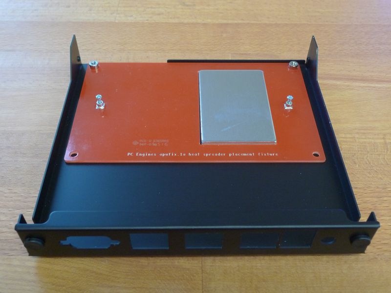
| + | Follow the [https://pcengines.ch/apufix1a0.htm PC Engine instructions for placing the heat speader to the bottom of the enclosure]: | ||
| + | |||
| + | https://pcengines.ch/pic/apufix1a2.jpg | ||
| + | |||
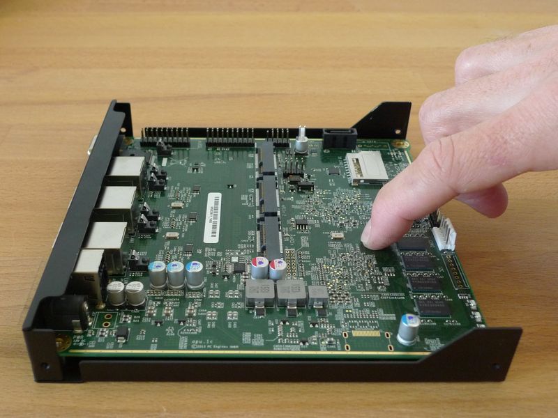
| + | Follow steps 1 and 4 of the [https://pcengines.ch/apucool.htm PC Engines instructions to attach the board to the enclosure], specifically: | ||
| + | |||
| + | # Remove the DB9 port's two hex nuts; | ||
| + | # Place the board on the bottom part of the enclosure such that the ports fit into the port cut outs: | ||
| + | |||
| + | https://pcengines.ch/pic/apucool4.jpg | ||
| + | |||
| + | # Attach the four truss head screws (they look like they have little hats) to the bottom of the enclosure to secure the four corners of the board; | ||
| + | # Attach the three black rubber plugs to the three circular holes on the back side of the enclosure. There is one on each side and one on the middle. | ||
| + | |||
| + | === Write the image to the SD Card === | ||
| + | |||
| + | You will need to write your SD card with the x86 image and then boot it. | ||
| + | |||
| + | === Secure enclosure === | ||
| + | |||
| + | # Place the bottom part of the enclosure on a table with the port side of the enclosure on the right side and the open front side on the left; | ||
| + | # The top part of the enclosure is open on one side. We will call that side the back and its opposite side the front; | ||
| + | # Place the top part over the bottom part such that the back is half way over the board; | ||
| + | # Slide the top part to the right so the front secures to the front of the bottom part and the back of the top slides over the bottom back; | ||
| + | # Secure the top part to the bottom part by screwing in the four tiny flat head screws; | ||
| + | |||
| + | === Power it up === | ||
| + | |||
| + | # Attach the power adapter wire to the power port next to the USB ports; | ||
| + | # Plug the power adapter into an electrical socket; | ||
| + | # The single light on the middle-ish of the front should turn on. | ||
| + | |||
| + | Place the top part of the enclosure over the bottom part so that such that the open side fits over the port side of the bottom enclosure | ||
Revision as of 12:05, 12 March 2023
Note: These are only available from the manufacturer. You can pick a version [here] that matches your specific needs.
Contents
Files
Instructions
The APU should be well supported since it has an x86 CPU. The installation process should be similar to the Raspberry Pi 4 Model B-focused Node Setup instructions.
Securing the APU2 board to its enclosure
Follow the PC Engine instructions for placing the heat speader to the bottom of the enclosure:
https://pcengines.ch/pic/apufix1a2.jpg
Follow steps 1 and 4 of the PC Engines instructions to attach the board to the enclosure, specifically:
- Remove the DB9 port's two hex nuts;
- Place the board on the bottom part of the enclosure such that the ports fit into the port cut outs:
https://pcengines.ch/pic/apucool4.jpg
- Attach the four truss head screws (they look like they have little hats) to the bottom of the enclosure to secure the four corners of the board;
- Attach the three black rubber plugs to the three circular holes on the back side of the enclosure. There is one on each side and one on the middle.
Write the image to the SD Card
You will need to write your SD card with the x86 image and then boot it.
Secure enclosure
- Place the bottom part of the enclosure on a table with the port side of the enclosure on the right side and the open front side on the left;
- The top part of the enclosure is open on one side. We will call that side the back and its opposite side the front;
- Place the top part over the bottom part such that the back is half way over the board;
- Slide the top part to the right so the front secures to the front of the bottom part and the back of the top slides over the bottom back;
- Secure the top part to the bottom part by screwing in the four tiny flat head screws;
Power it up
- Attach the power adapter wire to the power port next to the USB ports;
- Plug the power adapter into an electrical socket;
- The single light on the middle-ish of the front should turn on.
Place the top part of the enclosure over the bottom part so that such that the open side fits over the port side of the bottom enclosure